The control system serves as the hub of a production facility, responsible for making decisions, issuing commands, and receiving feedback from the field. The reliability of this system depends not only on the selection of PLCs, drives, or switchgear components but also on the proper installation, operation, and maintenance of all these devices within a well-designed control panel architecture. Tempa Pano’s control system approach provides infrastructure solutions to meet the needs of various projects—ranging from operator control consoles to mechanical systems officially designated as “DDC-PLC-DSC Panels,” from motor control centers to low-voltage distribution panels. Oskon, on its part, integrates process information, electrical design, automation software, safety features, and commissioning processes into this same infrastructure framework.
This catalog guide explains how to select the right control panel, rather than just choosing a single product. The goal is to determine a system that suits the specific project requirements by considering factors such as field conditions, functions, thermal loads, maintenance accessibility, and potential future expansions in the same evaluation framework. There are significant differences between applications such as mass production lines, process plants, building automation systems, logistics centers, and machine installations. Therefore, the control scenario and equipment list must be carefully defined before determining the external dimensions of the control panel.
Overview of the control systems range
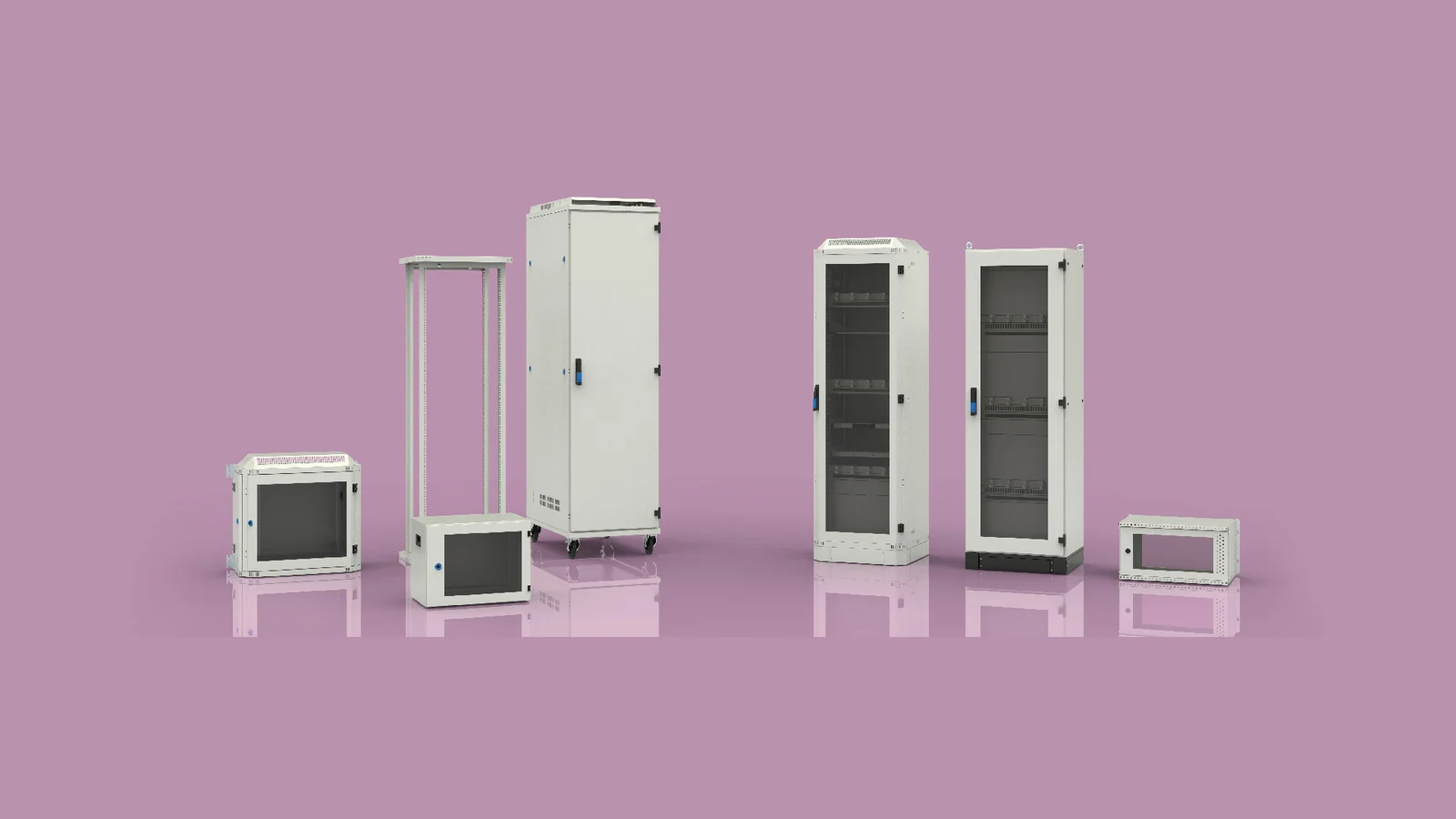
On Tempa’s official solution pages, control panels are categorized under the titles “DDC-PLC-DSC Panels,” MCC panels, and LVP5000 systems. It is important not to automatically equate the manufacturer’s use of the term “DSC” with the commonly used DCS abbreviation in process automation; instead, the control architecture to be applied should be explicitly specified in the product description. These different product groups differ in terms of power distribution, signal density, operator interaction, and maintenance requirements. While ergonomics and indicator layout are key considerations for a control panel, for a PLC panel, it is essential to separate low-voltage signals from power circuits. In the case of MCC panels, high-current pathways and proper circuit segmentation become critical factors.
The families listed in the catalog cannot replace a ready-made project. The same housing can perform vastly different functions depending on its internal configuration. Therefore, the required specifications must include details such as supply voltage, total power, number of motors, control architecture, communication system, ambient temperature, dust and humidity conditions, cable entry direction, installation area, and maintenance requirements. The final selection must be verified in accordance with the applicable project standards and risk assessment criteria.
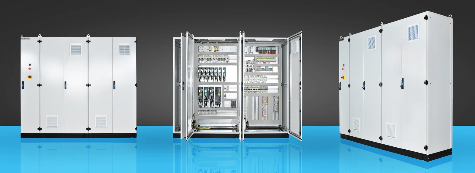
Control desks: the interface between operator and process
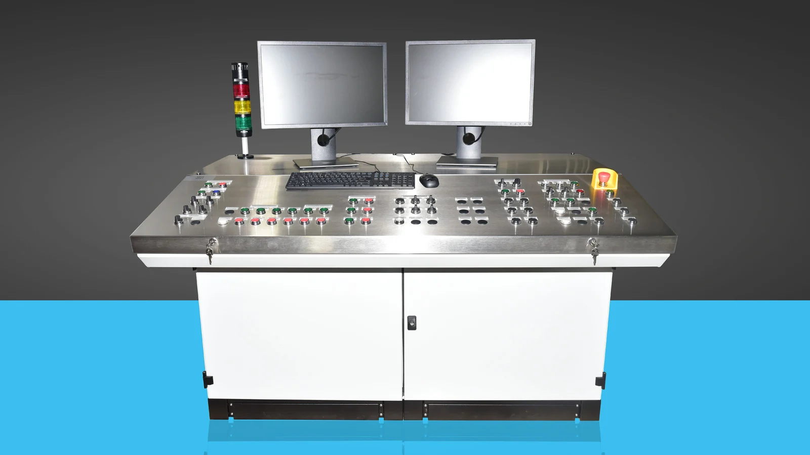
The control panel is the physical interface through which the operator monitors and intervenes in the production line. The arrangement of components such as screens, buttons, selector switches, indicator lights, emergency stop buttons, and industrial computers is determined based on factors like visibility and frequency of use. Components that are too large or difficult to reach can pose ergonomic issues in daily operation; similarly, the close proximity of similar controls may increase the risk of errors. During the design process, it is essential to consider not only whether the equipment fits within the available space but also how it will be used throughout the shift.
The interior of the control panel is just as important as its front surface. Factors such as the heat generated by monitors and computers, the bending radius of cables, service access covers, proper earthing, and the separation of data and power cables must all be taken into consideration. The choice of materials for surfaces in areas that require frequent cleaning varies in heavy industries, where considerations include resistance to impact, vibration, and ease of access. The location of the operator’s desk should also be determined in conjunction with machine safety analysis, and emergency stop and reset functions must be designed in accordance with relevant safety regulations.
The DDC-PLC-DSC product heading and DCS application context
PLC panels are used for fast, deterministic control in machine and line automation, while DDC panels are employed for direct digital control in building and auxiliary facility automation. In process applications, DCS—i.e., distributed control system architectures—provide large-scale control and monitoring capabilities. The term “DSC” in Tempa’s official website title should be retained as the name of a product category; the actual control architecture of a project should be specified separately as DDC, PLC, or DCS. A common requirement for panel design is that the controller, remote I/O devices, power supplies, communication equipment, and field terminals be arranged in a logical topology. The terminal block layout and the I/O list must be mutually consistent, and the cable channels should be designed to allow sufficient capacity and accommodate potential future modifications.
Cables for analog measurements, fast counters, safety I/O circuits, and industrial Ethernet cables must be routed in a manner that protects them from electromagnetic interference. Collecting power electronics and sensitive signal equipment in the same space without proper planning can lead to inaccurate measurements and communication issues. When necessary, physical separation, shielding, proper grounding, and selecting an appropriate EMC-compliant control panel family should be considered. Thermal calculations must be based on the environmental conditions permitted by the controller manufacturer as well as the actual temperature of the site where the panel will be installed.
MCC panels: organised, serviceable motor control
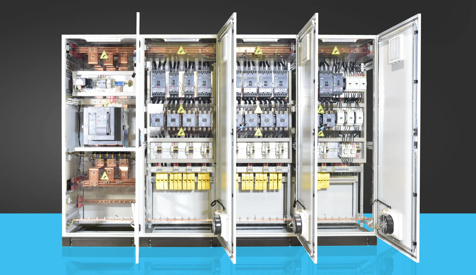
The motor control center integrates the power supply and control of multiple motors within a common architecture. Components such as main fuses, busbars, motor protection devices, contactors, soft starters or drives, as well as measurement and communication elements, are arranged according to the specific requirements of the project. Factors such as the required motor power, starting current, short-circuit levels, and selectivity also determine the design of the control panel. The choice of whether to use partitioned, drawer-type, or fixed-mounted configurations directly affects which sections can be safely de-energized during maintenance.
In the design of an MCC, the area for cable connections should not be determined retrospectively. Large-diameter power cables, cable connectors, and current transformers require considerable space. The direction of entry, the height of the panel, the base, and the route for cable routing must be confirmed during site surveys. Additionally, the harmonic and thermal effects of the drives, the braking resistance, as well as the ventilation and communication topology must also be taken into consideration. To ensure that faults can be quickly identified in the event of an issue, labels, one-line diagrams, terminal block numbers, and device codes must all conform to the same documentation standards.
LVP5000 and low-voltage panel design
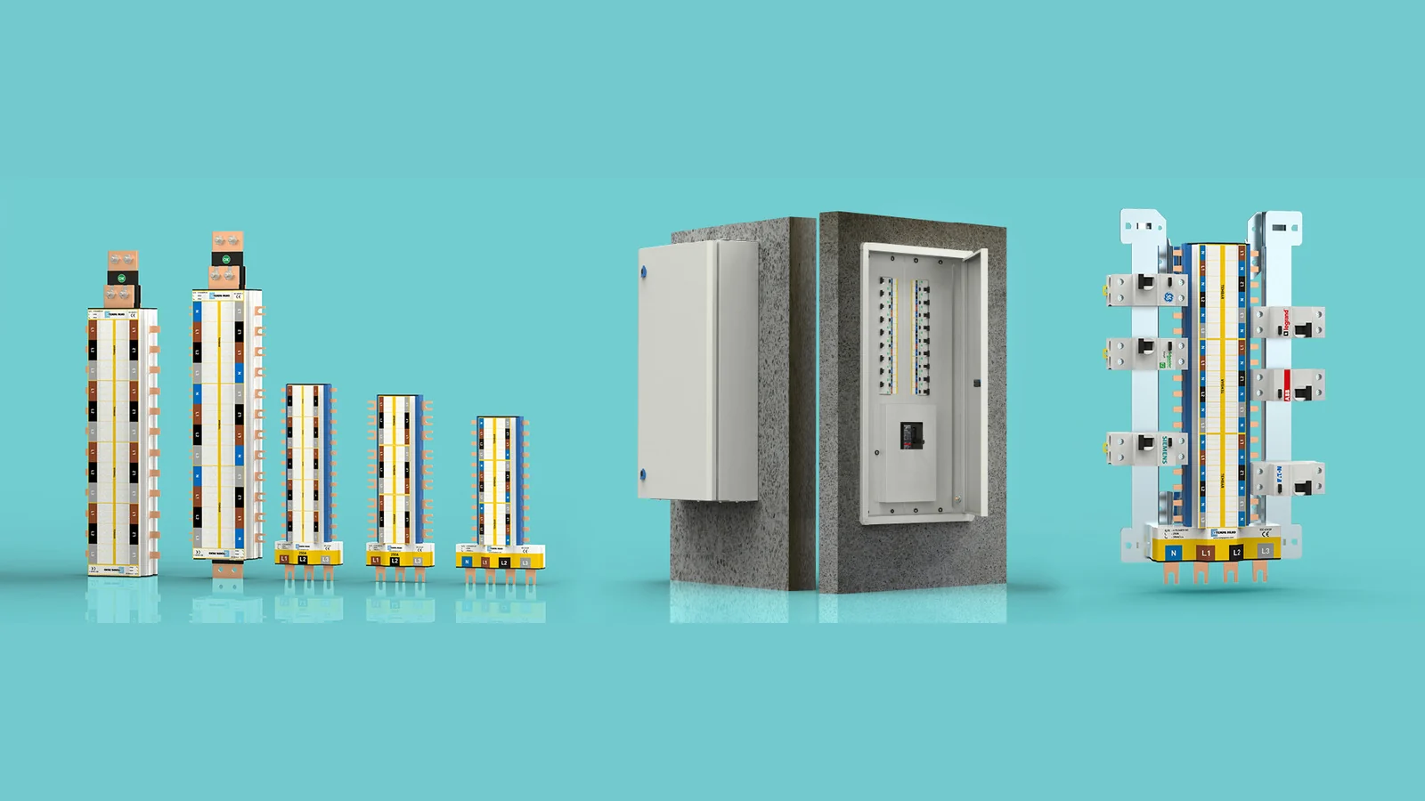
The LVP5000, listed under Tempa’s control systems category, is categorized as a low-voltage panel solution. In such systems, main distribution, branch outputs, measurement functions, compensation mechanisms, and motor control capabilities can all be integrated within a single panel. The specific functions to be included in the same panel are determined based on factors such as operational continuity, functionality differentiation, access permissions, and maintenance considerations. It is not advisable to prepare a quote solely based on external dimensions without first completing the single-line diagram, load list, and short-circuit calculation.
Nominal current is not the only factor to consider when making selections. Other variables such as busbar cross-section, ambient temperature, the way enclosures are arranged side by side, the increase in temperature inside the cabinet, the power loss of protective devices, and the installation altitude can all affect the overall capacity. The design validation and testing methods required by relevant standards must be defined at the beginning of the project. Oskon ensures that the component selection aligns with the process and automation requirements of the specific application, thus preparing a technical package that is perfectly suited for panel manufacturing.
Power factor correction and auxiliary control panels
Reactive power compensation is a distinct field of engineering that affects power quality and grid utilization. Factors such as capacitor banks, contactor or thyristor switching, reactive power requirements, harmonic measurements, and cooling systems must all be taken into consideration. In existing facilities, it is essential to measure not only the billable value but also the load profile and harmonic spectrum. Incorrect selection of capacitor banks or inadequate cooling systems can lead to unnecessary heating inside the control panel and premature wear of components.
Mimic control panels, local control boxes, field distribution panels, and specialized test consoles can also be part of the control architecture. In these applications, it is specified how the operator accesses information, where field devices are located, and which controls should be used in the event of a fault. For each specific application, the material used for the enclosure, the door configuration, the mounting plate, the seals, the locks, and the cable connections are all selected separately.
Selection table for the right control panel
| Application | Primary design consideration | Data required for the project |
|---|---|---|
| Operator console | Ergonomics, visibility, and operator safety. | Screen and command list, frequency of use, operator position |
| DDC/PLC/DSC product group; DCS applications | Signal integrity, network, I/O density, heat. | I/O list, topology, power losses, expansion ratio |
| MCC | Short circuit, wiring, motor power supply, and service components. | List of motors, method of starting, cable cross-sections, selectivity |
| Low-voltage distribution | Busbar, protection coordination, operational continuity | Single line, load profile, short-circuit level, form requirements |
| Compensation | Harmonics, capacitor bank stages, and cooling | Energy measurement, load variation, harmonic analysis report |
Thermal management and site conditions
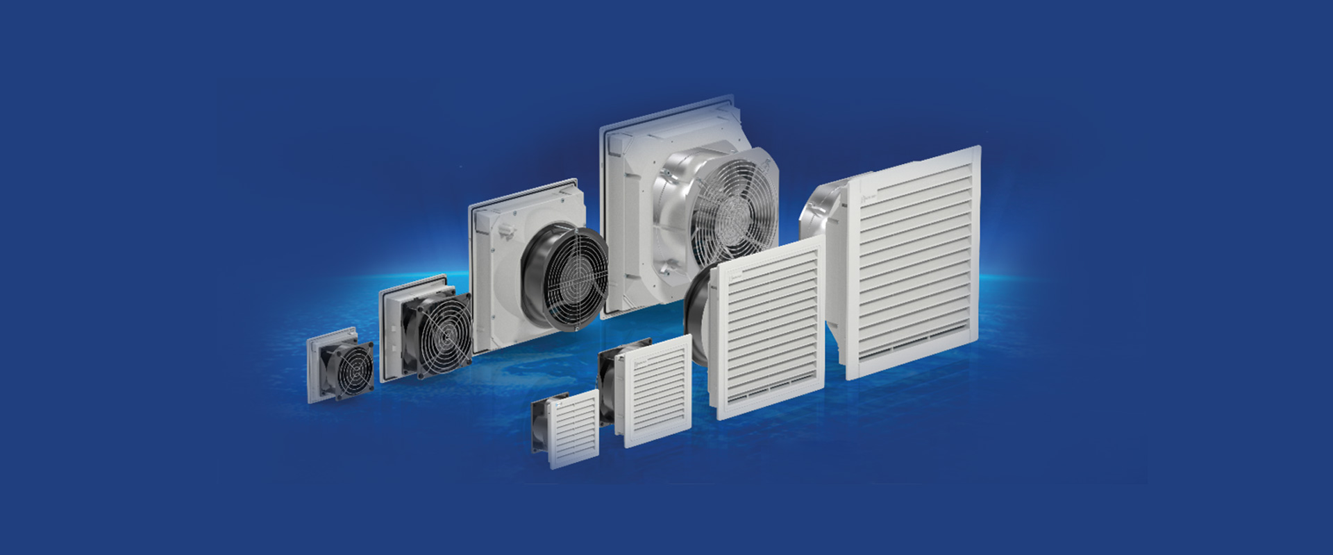
Every device inside the control panel generates some amount of heat. It is necessary to account for the power losses of the drive, power supply, transformers, and protective components; at the same time, the natural heat emission from the panel’s surface, as well as ambient temperature and solar radiation, must also be taken into consideration. Based on these factors, options such as natural ventilation, fan-filter systems, panel-mounted cooling units, or heat exchangers can be selected. Simply adding a cooling device is not sufficient; it is essential to carefully examine the inlet and outlet locations, as well as the heat dissipation areas of the devices, to prevent air circulation disorders.
In dusty, oily, humid, corrosive environments, or in outdoor conditions, the material used for the enclosure and the level of protection required will vary. Devices located on the cable glands, ventilation openings, and doors affect the overall protection level of the control panel. If stainless steel or EMC-compliant solutions are necessary, these choices are made in conjunction with the internal design of the control panel. Uncontrolled holes that are subsequently made in the field can reduce the protective effectiveness of a properly selected enclosure.
Project workflow with Oskon
The process begins with site investigation and function definition. Load and I/O lists are verified, a single-line and control architecture is designed, and the approximate power losses of components are calculated. The appropriate Tempa Pano model is selected based on requirements for size, materials, protection, and accessibility. Subsequently, details such as mechanical layout, cable pathways, terminal blocks, busbars, grounding, labeling, and thermal management are specified. After the design is reviewed, the manufacturing documentation is finalized.
During the FAT phase, the energy distribution system, I/O functions, communication mechanisms, alarm systems, safety features, and documentation are verified through controlled scenarios. On-site, cable inspections, SAT tests, and commissioning procedures are carried out. The delivery is completed with up-to-date schematic diagrams, software backups, parameter settings, test records, and maintenance information. As a result, the control panel is not merely a delivered cabinet but becomes a fully operational and monitorable system.
Preparation checklist before requesting a quotation
- A single-line or block diagram that illustrates the function of the application and the boundaries of the control panel.
- Lists of loads, motors, I/O devices, communication systems, and operator equipment.
- Information on power supply, short circuits, the neutral wire, and the grounding system.
- Ambient temperature, humidity, dust, chemical influences, and definitions of internal/external environments.
- Cable entry direction, field layout, dimensions of the base frame, and service corridor.
- Protection level, material, color, locking features, and access requirements.
- Redundancy, expansion capacity, maintenance approach, and target commissioning date.
Together, these details allow enclosure selection, internal layout, and automation scope to be assessed on a common technical basis. Oskon’s factory automation, Automation consulting and commissioning capabilities turn Tempa’s enclosure portfolio into an integrated control system operating in the field.
Official product sources: Product families and images are based on Tempa Pano’s Control Panels, DDC-PLC-DSC Enclosures, MCC Enclosures and LVP5000 pages. Final technical values must be verified against project conditions and current manufacturer documentation.