The selection of industrial sensors is a more complex process than simply determining a product code based on the detection range listed in a catalog. First, it is necessary to clarify for what specific physical parameter measurement is required, whether the control system expects discrete or continuous data, what acceptable error margins and response times are needed, as well as the installation location, environmental conditions, and the desired response in the event of a fault. This selection guide discusses Festo’s cylinder sensors and position detectors, as well as pressure/vacuum sensors and flow rate sensors separately. The numerical examples provided are specific to the variants identified by their names and product numbers; the final product selection should be confirmed in accordance with the latest Festo data sheets, instruction manuals, and actual application requirements.
Define the measurement task before selecting a sensor
Questions such as “Is the part in place?”, “Has the cylinder completed its stroke?”, “What is the piston’s position?”, “Is the line pressure sufficient?”, “Is the part truly held in place by vacuum?”, and “Why has the air consumption increased?” cannot be answered by the same type of sensor. A cylinder sensor typically sends a binary signal indicating whether the piston magnet has passed a specific point. A position sensor can generate a continuous position value within its designated detection range. Pressure and vacuum sensors measure the pressure of the fluid, while a flow rate sensor determines the amount of fluid that passes through a given area per unit of time. Without making this distinction, even if the selected sensor is mechanically installed correctly, it may not provide the necessary information for making an informed decision.
The requirement document should specify the measured parameter, the normal operating range, the expected minimum and maximum values, short-term overloads, the required resolution, the acceptable total error, and the sampling requirements. It should also clarify whether the sensor is intended for mere monitoring, initiating a cycle, generating quality records, or being used in a safety function. The presence of a standard automation sensor alone does not guarantee the required performance level of a safety function; safe applications can only be established with appropriate products, architectures, diagnostic capabilities, and validation procedures.
| Measurement task | Suitable initial product family | Critical selection data |
|---|---|---|
| End or intermediate position of the pneumatic cylinder | Magnetic cylinder sensor | Drive compatibility, switch window, PNP/NPN, cable, and environment. |
| The continuous position of the piston throughout the stroke | Position transmitter; for example, SDAT-MHS | Detection range, analog/IO-Link output, resolution, linearity, and mounting options. |
| Supply pressure, process pressure, or vacuum level | Pressure/vacuum sensor; for example, the SPAN type. | Relative/absolute measurement, range, fluid, pressure port, output, and overload protection. |
| Pressure air consumption, leaks, or minimal airflow. | Flow sensor; for example, SFAH | Flow range, flow direction, gas type, reference conditions, pressure-temperature parameters, and connections. |
Distinguish cylinder sensors from position transmitters
Festo’s sensor portfolio page describes how cylinder sensors can be used in pneumatic drives to provide binary feedback regarding the piston’s position. The sensor detects the magnetic field generated by a permanent magnet inside the piston and generates an electrical signal at the switching point. This approach represents a simple and repeatable solution for verifying whether the piston has reached the front end, the rear end, or a specific intermediate position. However, the status indication “sensor active” does not provide the piston’s exact coordinates throughout its stroke; it merely indicates that the condition has been met within the designated detection range.
It is not always the right approach to place a proximity sensor as close as possible to its mechanical stop. The detection range of the piston magnet must be taken into consideration, along with the switching time, which varies depending on factors such as speed, pressure, load, and cushioning behavior. The sensor is adjusted to ensure it operates within the reliable range required by the control logic, and then tested at minimum and maximum operating pressures, as well as under the lightest and heaviest loads. If both proximity sensors become active simultaneously, if no signal is received within the expected time frame, or if their status changes without a corresponding command, the PLC should interpret these events as separate faults.
The position sensor continuously monitors the movement of the piston magnet over a certain range, providing analog or digital measurement values. This approach can be utilized to detect differences in the thickness of a component during clamping processes, to monitor the intermediate positions of a cylinder, or to obtain more detailed information about its movement. It should be noted that the detection range and the total stroke of the cylinder are not the same concept. The effective measurement area of the sensor must be carefully controlled to ensure compatibility with the geometry of the piston magnet and the selected drive mechanism; moreover, its mounting position must be mechanically secured after any calibration or adjustment procedures.
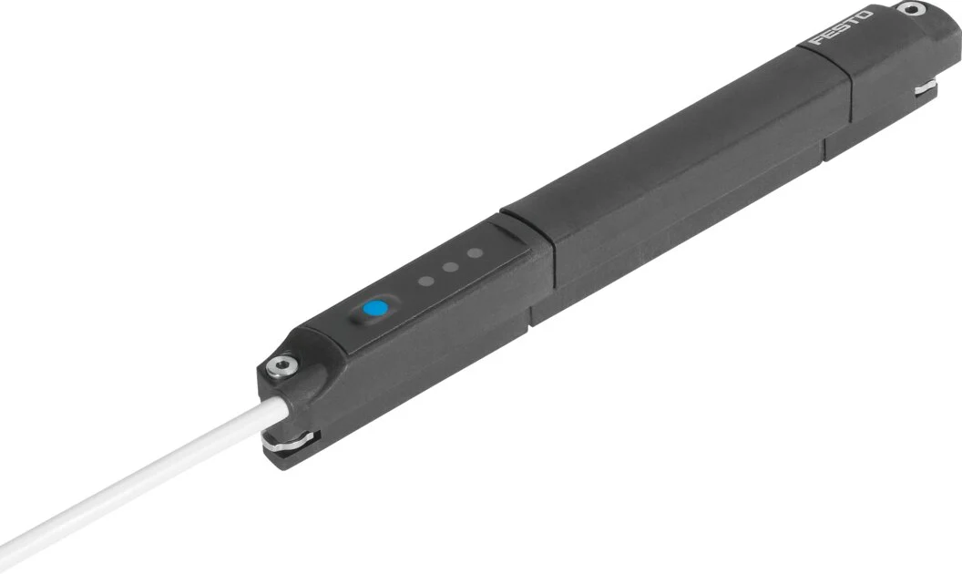
Variant example: SDAT-MHS-M100-1L-SA-E-0.3-M8
On Festo’s data page dated August 10, 2026, it is specified that the variant with product number 1531267 has a measurement range of 0–100 mm, a magnetic measurement principle, and supports IO-Link Device V1.1. The product offers a 4–20 mA analog output, a programmable PNP switching output, and IO-Link functionality. Typical specifications include a sampling rate of 1 ms, a path resolution of 0.05 mm, and a repeatability accuracy of 0.1 mm. These values must not be automatically applied to other detection ranges or other output configurations within the SDAT product family.
If the analog version of a position sensor is to be connected to a PLC, it is necessary to verify the current or voltage type, resolution, common reference, and error detection range of the input module. The conversion of the measured value into physical millimeters must be specified in the commissioning documentation. When using IO-Link, the process data, as well as the identity and identification information, are matched based on the current IODD values, indicating which bytes and bits contain this information. After replacing the sensor, if data retention or parameter reloading is required, it is essential to test the IO-Link master functionality, access rights, and ensure correct device pairing.
Selecting the range for pressure and vacuum sensors
A pressure sensor converts the fluid pressure at the measurement port into an electrical value. According to Festo’s official description of pressure/vacuum sensors, the SPAN series uses piezoresistive cells for relative pressure measurements in compressed air and non-abrasive gases. It is capable of transmitting the measurement results via switch signals, analog signals, or IO-Link. The term “relative measurement” refers to the fact that the measurement is referenced to the ambient pressure. If absolute pressure or a different reference value is required, it is not sufficient to simply consider the measurement range; the appropriate type of reference system for the sensor must also be selected.
The range is determined in such a way that a significant portion of the normal value is utilized within the sensor’s measurement range. While a very wide range may appear physically robust, it can make it difficult to detect minor changes in the application; on the other hand, an excessively narrow range poses a risk of excessive loading during peak conditions. In a supply line, compressor fluctuations, valve switching, and rapid filling pressure surges can occur. In vacuum applications, factors such as hose volume, ejector capacity, the porosity of the workpiece, and any leaks can all affect the performance at the moment of gripping. The threshold value should not be set based on a single measurement taken in the idle state alone.
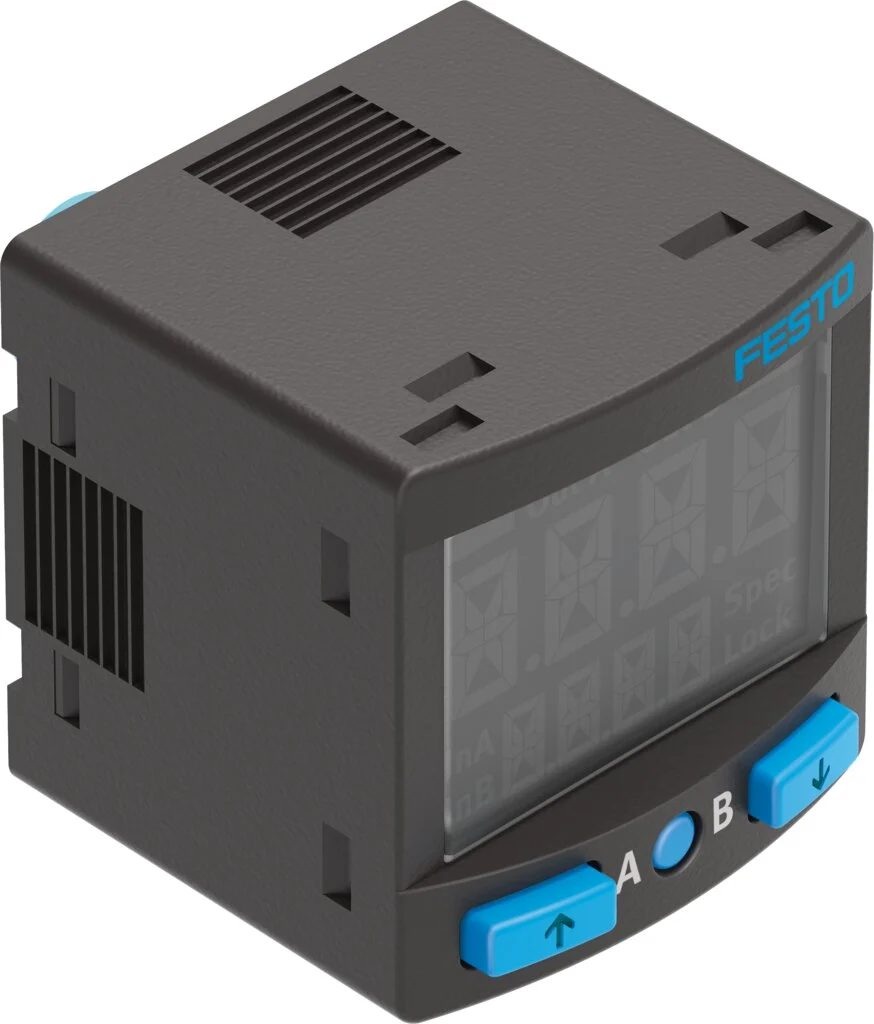
SPAN-B2R-Q4-PN-PN-L1, product number 8035553, covers pressure and vacuum through the B2R range in its code. This variant has a Q4 pneumatic connection and two switching outputs; do not confuse it with other SPAN codes. A sensor family may offer different threads, tube connections, measurement ranges, PNP/NPN, analog and IO-Link options. Specify the full code, port orientation, cable/plug type and adjustment access in the design drawing.
When determining the threshold for vacuum handling, the distributions of “part present” and “part absent” must be measured using actual products. The safe gripping threshold is adjusted in such a way that it does not cause delays during fast cycles, nor does it misinterpret vibrations resulting from surface leaks. In pressure-based systems, the low-pressure alarm threshold should not be set equal to the nominal regulator value. The lower limit at which the machine can generate a sufficient gripping force must take into account the total sensor error and dynamic pressure drops.
Flow sensors: distinguish instantaneous flow from consumption
Flow measurement can be used to verify whether a gripper is actually drawing in air, to monitor minor leaks, to compare machine consumption, or to establish trends before maintenance. However, instantaneous flow rate, cumulative consumption, and pressure are not the same concept. Whatever reference condition is used to determine the volumetric flow rate, the same definition must be applied throughout the PLC control, display system, and reporting process. Otherwise, when comparing data from different sensors or different facilities, significant discrepancies may arise.
Festo positions its SFAH family of sensors for compact flow monitoring in applications involving compressed air and non-abrasive gases. According to the official product description, this family of sensors can transmit switching signals, analog signals, or data via IO-Link, depending on the selected model, and offers a range of different flow measurement ranges. When selecting a sensor, it is essential to verify the permitted flow direction, operating pressure, ambient and fluid temperatures, gas type, as well as the pneumatic connection requirements of the sensor. In addition, a sensor or cable gland with a reduced diameter should not impose any additional restrictions on the system it is intended to monitor.
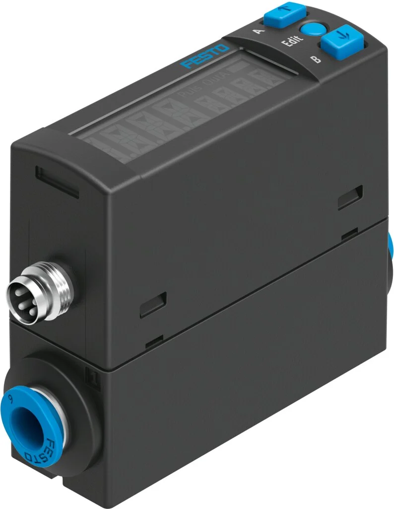
Variant example: SFAH-10U-Q6S-PNLK-PNVBA-M8
The 11 August 2026 data sheet for product number 8058470 specifies mass and volumetric flow measurement using a thermal principle, with unidirectional flow. Measurement range is 0.2–10 l/min and operating pressure is −0.9–10 bar. Permitted media include compressed air of the stated quality class, nitrogen and argon. It provides two switching outputs configurable as two PNP or two NPN outputs, plus IO-Link. These ranges and media apply only to variant 8058470.
In a leak monitoring application, baseline values must be recorded under various loads and operating cycles under normal production conditions. It is natural for the flow rate to change when pressure, temperature, or the number of active consumers varies. The alarm logic can be linked to the machine’s status, the product recipe, and specific time frames, rather than relying on a fixed threshold. Continuous flow when the valves are closed may indicate a leak, while an increase in peak flow during a cycle could suggest faster adjustments, a more powerful drive, or worn-out components. Sensor data alone cannot determine the exact location of the fault, but it provides a concrete basis for initiating investigations at the right time and under the right conditions.
Choosing switching, analogue and IO-Link outputs
The switch output represents the simplest solution for making binary decisions, such as whether a threshold has been exceeded or not. It is essential to ensure compatibility with PNP or NPN input types of PLCs; the normally open/normally closed behavior, as well as the logic for detecting cable disconnection and power loss, must be carefully selected. Window comparison allows for decisions to be made within or outside a specific range, while hysteresis helps prevent the output from switching rapidly in the presence of measurement noise. Additionally, the current limit of the output may not be suitable for directly driving a load; in such cases, the data sheet must be taken into consideration.
Analog signals are useful for continuous measurement processing in the control system. Assess 0–10 V signals for voltage drop and electromagnetic interference, and 4–20 mA signals for current-loop behavior, input resistance and wire-break diagnostics. Shielding, grounding and power/signal cable routing must follow plant EMC rules. Record the analog scaling, sensor-display unit and PLC engineering unit together during commissioning.
IO-Link is capable of transmitting device identity, status, parameters, and certain diagnostic information alongside the measured values, via standard point-to-point communication. To take advantage of this feature, it is necessary to specify the correct master port class, IODD version, cycle time, process data map, and parameter configuration. However, IO-Link does not automatically ensure accurate measurements; physical installation, range setting, and calibration remain essential requirements. Additionally, the PLC program must include identity verification mechanisms to prevent the automatic loading of incorrect parameter settings in the event of a master or sensor replacement.
Installation, pneumatic connections and environmental conditions
In the case of cylindrical sensors, the correct socket and mounting device are not merely designed for mechanical convenience; they also determine the distance between the sensor and the piston magnet. Even if the sensor can be installed from the top, the clamping torque, the direction of the cable outlet, and the bending radius must be applied in accordance with the product specifications. It is essential to verify that the variant selected for use in a movable cable carrier is suitable for continuous bending and torsional forces. Since strong external magnetic fields, welding currents, or ferromagnetic components may affect the sensing performance, actual tests in the real machine environment are necessary.
For pressure and flow sensors, flow direction, sealing and stress-free mounting matter as much as port size. Use the designated wrench flats for threaded connections; do not turn the sensor by its cable or display. Relieve tensile load between tubing and sensor, and assess condensate, particles and oil at the measuring cell. Avoid sudden pressure shocks, provide the recommended air quality and use a suitable upstream filter when required to support stable measurement.
The IP protection class is only meaningful for a properly installed and correctly connected product. An open connector, an incorrect seal, or an inappropriate cable gland can reduce the level of protection provided. The ambient temperature and the temperature of the fluid in question may also have different requirements. If the application requires a clean room, an environment in close contact with food, protection against welding sparks, cooling oils, chemical cleaning agents, or explosive substances, a standard variant should not be assumed to be suitable. The full product code should be used to verify that the material composition, certifications, and environmental specifications meet the specific project requirements.
Commissioning: establish a reliable reference first
- Verify device identity: The product number, measurement range, pneumatic port, output type, supply voltage, and cable pins are compared with the electrical-pneumatic schematic diagram.
- Inspect the installation: The sensor position, flow direction, connection torque, hose/cable tension, connector integrity, and screen visibility are all checked.
- Read the raw value: Before setting the teaching or threshold values, measurements in the idle, normal, and limit states are recorded first.
- Match the scale: The analog or IO-Link raw value is converted into the correct physical unit; the decimal value and the reference condition are checked.
- Set the thresholds: The alarm and switching levels are determined by taking into account tolerances, sensor errors, process distribution, hysteresis, and filter time.
- Try to reproduce the fault. Scenarios such as cable breakage, low power supply, blocked lines, leakage, incorrect wiring directions, and sensor replacements are all verified in accordance with safe procedures.
Once the commissioning process is completed, not only the final parameter value but also the measurements used to determine that value must be retained. The values of samples of normal products, products accepted at the limit, and defective products, along with the corresponding pressure, temperature, load, and cycle conditions, are all recorded. This enables subsequent maintenance teams to determine whether any change in critical parameters is due to actual process requirements, sensor malfunctions, or mechanical wear and tear.
Follow the measurement chain when diagnosing faults
If no value is detected at all, first check the supply voltage, pin configuration, PLC input type, and the continuity of the cable. If a value is detected but does not correspond to the expected physical behavior, then investigate possible issues such as the incorrect measurement range, unit of measurement, analog input configuration, or the IO-Link process data map. For cylinder sensors, possible causes include mechanical looseness or misalignment of the piston magnet; for pressure sensors, a clogged port or condensation; and for flow sensors, reverse flow direction, incorrect gas selection, or restrictions in the pipeline.
It is not appropriate to simply use software filters to suppress uncertain signals. First, it is necessary to identify the underlying causes, such as actual process vibrations, pressure fluctuations, electromagnetic interference, loose connectors, incorrect grounding, or operation near critical thresholds. When the filtering duration is increased, the impact of the detection delay on the machine’s cycle and protection mechanisms must be measured. For accurate diagnosis, it is essential to compare the values displayed on the sensor screen with those obtained through IO-Link communication, the raw data from the PLC, and independent reference measurements.
Checklist for quotations and bills of materials
- The control decision depends on the physical parameter to be measured, the intended application, and the value detected by the sensor.
- Normal, minimum, maximum values, as well as short-term overload levels; required accuracy and response time.
- Cylinder model, sensor socket, piston magnet, detection position, and mounting device.
- Detection range for the position sensor, analog scale, requirement for IO-Link, and compatibility with the drive system.
- Reference types for pressure and vacuum applications, including fluid types, ports, pressure peaks, and threshold-hysteresis values.
- For flow measurement, parameters such as gas flow rate, flow direction, range, reference conditions, pipe diameter, and expected pressure drop are required.
- PNP/NPN, 0–10 V, 4–20 mA, or IO-Link; connector, cable length, and compatibility with PLC/master device.
- Ambient and fluid temperatures, IP rating, vibration, EMC, chemical resistance, washability, and resistance to explosive environments.
- Parameter backup, access control, alarm records, spare parts, and replacement procedures.
When this information is collected before the product code is finalized, the sensor ceases to be merely an accessory that fits within a machine; instead, it becomes an automation component with clearly defined measurement purposes, acceptance criteria, and diagnostic methods. Festo’s product portfolio offers a wide range of options for various measurement tasks. Reliable results can only be achieved by selecting the right sensor family, verifying the appropriate model, and converting the collected data into meaningful information for the control system.