Motion control goes beyond starting and stopping a motor. Position, speed, torque, synchronization, electronic camming, kinematics, safe motion and cycle time must serve the same machine requirements. Siemens combines SIMATIC controllers, SINAMICS drives, SIMOTICS motors, PROFINET communication and TIA Portal engineering in a scalable system. A suitable solution starts by quantifying the mechanical load and motion profile, then matching each axis to the appropriate hardware class.
Create the motion profile before the product list
When selecting a servo axis, the motion profile should be the primary reference document, rather than the motor catalog. The starting and target positions, movement time, maximum speed, acceleration/deceleration rates, waiting times, the number of repetitions within a cycle, and the desired stop position in emergency situations must all be specified. For rotary axes, the diameter and transmission ratio must be taken into account; for linear axes, the pitch of the screw, the pulley ratio, or the specifications of the linear motor should be considered. The mass of the load alone is not sufficient—the moment of inertia of the load relative to the axis, friction, unbalanced forces, the effect of gravity, and external process forces all affect the required torque.
It is a common mistake to confuse the nominal torque value listed in the catalog with the short-term peak torque. A shaft that requires high torque during acceleration may operate at low load during the rest of the cycle; however, the thermal models of both the drive and the motor must be considered for the entire cycle. Similarly, a high-resolution encoder cannot automatically compensate for loose mechanics, flexible belts, or large reduction gear clearances. The acceptance criteria should be based on the position and time accuracy of the product at the actual point of use, rather than the values measured on the motor shaft.
Standard, extended and advanced motion control
Siemens’ SIMATIC Controller selection approach addresses motion requirements at three levels. Standard Motion Control covers speed control, positioning, measuring inputs, cam outputs and basic synchronization. Extended functions support electronic camming and more complex synchronized movements; advanced functions address cross-CPU synchronization and multi-axis kinematics. Use this classification as an engineering decision that determines technology objects, axis count, cyclic processing load and licensing requirements.
| Motion task | Typical requirement | Siemens approach to consider | Limit to check |
|---|---|---|---|
| Speed or simple position axis | Single-axis, speed-controlled, point-to-point motion | SIMATIC standard motion control system and compatible SINAMICS drives | CPU technology resources, drive cycle and actual positioning accuracy |
| Synchronous axis | Electronic gear, marking, simultaneous cutting with the product. | S7-1500 or T-CPU technology objects and PROFINET IRT | Leading-value source, communication cycle, jitter and encoder architecture |
| Electronic camming | The tracking profile varies depending on the speed; this is due to changes in the product format. | SIMATIC S7-1500 T-CPU with extended Motion Control functionality | Cam-table resolution, recalculation and CPU resources |
| Kinematics | Cartesian, delta, or similar types of coordinated motion. | A T-CPU and the TIA Portal kinematic object that meet the required performance specifications. | Number of axes, working range, singularities, and mechanical calibration. |
| Safe movement | Safe Torque Off, safe stopping or Safely-Limited Speed | F/TF controller, PROFIsafe, and supported SINAMICS Safety Integrated functions | Risk analysis, selected drive license, sensor configuration, and validation procedures. |
| The existing SIMOTION facility | The continuity of the installed machine or its planned conversion. | Life cycle plan and objectives of the SIMATIC T-CPU architecture | Software functions, libraries, field network, and spare parts schedule |
SIMATIC S7-1500 T-CPU: machine and motion control in the same project
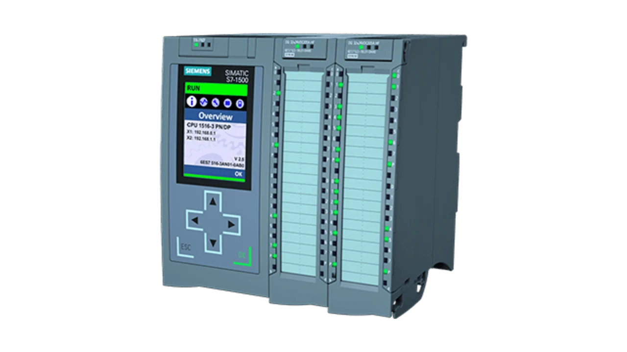
The SIMATIC S7-1500 T-CPU family combines the S7-1500 control platform with advanced motion control functions. In addition to the central panel-mounted T-CPU, there are also distributed options based on the ET 200SP, PC-based systems, and those integrated directly into the drive. This diversity allows for the selection of the most suitable controller type according to factors such as the machine’s layout, computational load, axis configuration, and maintenance requirements—not necessarily requiring the use of the same CPU for every application. The TF variants are also designed to enable the integration of fail-safe functions within the same control platform.
Technology objects in TIA Portal separate the user program from direct management of every low-level drive detail. Speed axes, positioning axes, synchronous axes, external encoders, cams and kinematics organize parameters, status words and command interfaces. Technology objects do not replace correct mechanical parameters. Check axis scaling, gear ratios, travel limits, dynamic limits and homing behavior against the machine drawings.
Select CPUs using more than the axis count
Two machines with the same axis count may place different loads on the controller. Ten simple positioning axes do not consume the same technology resources as ten axes using electronic camming, cross-CPU synchronization and kinematics. Siemens function manuals specify CPU Motion Control resources and the resource consumption of each technology object by version. Calculate the combined requirements of axis types, encoders, cams, measuring inputs and kinematics objects, with allowance for future expansion.
Consider the program cycle separately from the servo application cycle. CPU-intensive HMI, recipe, gateway or data-acquisition functions must not interfere with motion tasks. Monitor program-block execution times, communication load and technology-alarm behavior during commissioning. Providing only enough CPU capacity for the current machine can force unnecessary hardware replacement when a format or axis is added.
PROFINET IRT and drive communication
Synchronous operation requires that commands not only have the correct value but also be delivered at a predictable time. PROFINET IRT is used for deterministic communication in motion control applications, when appropriate controllers, network components, and drives are used. However, simply including “IRT” in the network name is not sufficient. The topology, the cycle time supported by the devices, the design of the synchronous communication framework, the selection of switches, and the distribution of network traffic must all be verified within the TIA Portal project. It should not be assumed that the same physical behavior as with standard office Ethernet can be achieved.
Cable routing, shielding, equal potential connections, and connector quality are also factors that affect the quality of motion control. Intermittent communication errors, random stops during production, or loss of axis synchronization can all be attributed to these factors. Diagnostic information from managed switches, port statistics, and PROFINET device details should be displayed on the HMI; a generic message like “drive fault” alone is insufficient.
SINAMICS S210: a system approach to dynamic servo axes
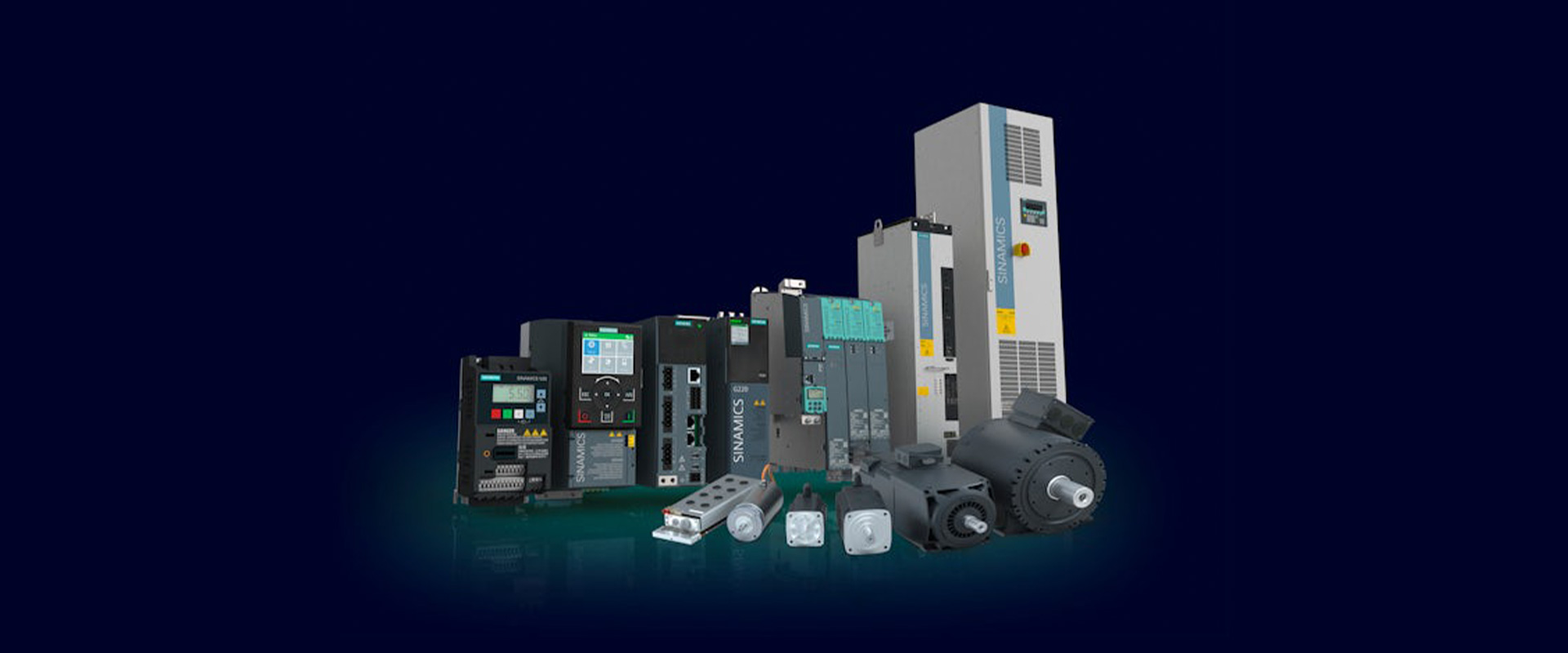
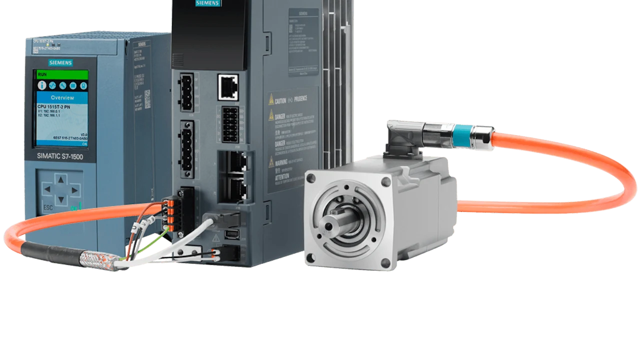
On Siemens’ official product page, the SINAMICS S210 is described as a servo drive system designed for complex and dynamic motion applications in the 0.1 kW to 7 kW power range. It can be connected to a SIMATIC control system via PROFINET IRT; according to the latest version 6.3, configurations that also support EtherNet/IP are available. The power class, network voltage, motor family, and communication options must be specified accurately in the order code. It should be noted that not all features available at the family level are necessarily included in every variant of this product.
Options include the S210 drive, as well as SIMOTICS S-1FK2, S-1FT2, or the hygienically designed S-1FS2 motors. The one-cable OCC connection method simplifies the wiring for power and encoder connections using appropriate system components. However, this convenience does not eliminate the need to consider factors such as cable length, cable type, connector orientation, brake wiring, and EMC regulations. The cables and motors must be selected as components of a certified servo system, rather than merely as accessories for the drive.
Safety Integrated: a feature list is not a safety function
The SINAMICS S210 family offers Safety Integrated functions for Safe Torque Off (STO), safe stopping and safe motion monitoring. Siemens states that certain extended functions require an optional license. A function being available in the product family does not automatically make the machine achieve PL e or SIL 3. Assess the risk evaluation, sensors, F-CPU, PROFIsafe communication, drive parameters, brake and mechanical stopping behavior together.
For example, STO aims to prevent motor torque generation safely; it does not mechanically hold a vertical load or stop rotating mass with a controlled ramp. If Safely-Limited Speed (SLS) is required, define the speed feedback source, response to exceeding the limit and relationship with the protective door. Acceptance testing must extend beyond pressing a safety button and observing the motor stop; also test single faults, feedback loss, restarting and stopping time.
Match SIMOTICS motors to load inertia and mechanics
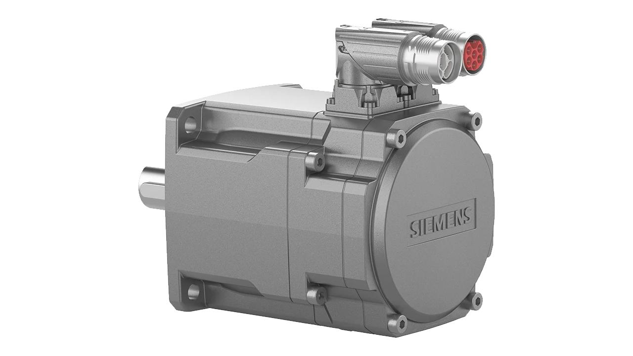
The SIMOTICS S-1FK2 is a compact, high-performance servo motor; the S-1FT2, on the other hand, is designed for applications that require a wider range of torque and inertia options. Siemens’ current product portfolio offers a variety of load-motor combinations across low, medium, and high inertia classes. A low rotor inertia can provide advantages for rapid acceleration, while a higher rotor inertia in mechanisms with variable or high loads can enhance stability. After all, the “fastest motor” is not necessarily the most suitable one for every application.
In the dimensioning of motors, parameters such as RMS torque, peak torque, maximum speed, thermal time constant, ambient temperature, altitude, mounting type, and braking requirements need to be considered. When a reducer is added, factors such as the reduction ratio, efficiency, backlash, allowable input speed, and output bearing loads also come into play. Encoder resolution and mechanical accuracy are distinct concepts. The thermal model must be verified against the actual motor data in the drive and the actual process cycle; in cases where high torque is required at low speeds over extended periods, the cooling conditions must be carefully evaluated.
Electronic cams, synchronisation and kinematics
Electronic gearing establishes a fixed ratio between the following axis and the leading-axis position. Electronic camming defines this relationship through a curve that changes with the product cycle. Flying saws, rotary cutters, print-mark correction, filling and capping, and packaging mechanisms are typical applications. When preparing a cam curve, check continuity of velocity and acceleration as well as geometric position: abrupt transitions can increase drive torque and mechanical vibration.
A kinematic object converts a target specified in Cartesian coordinates into the movements of multiple joints or linear axes. The type of kinematics used, the working range, the axis limits, and the singularity behavior are all determined by the version of T-CPU technology selected. The fact that the digital model appears accurate does not mean that the mechanical calibration is complete. The tool center point, zero points, mechanical offsets, and the actual coordinates of the part are all measured and processed by the system.
TIA Portal, tracing and virtual commissioning
Engineering controllers, drives and technology objects in the same TIA Portal project helps manage device names, telegrams, axis parameters and diagnostics in a common context. Monitoring and trace functions compare commanded position, actual position, speed, torque and following error on the same time axis. Save the trace as a graph and include it in the acceptance record together with the recipe, load, software version and sampling conditions.
S7-PLCSIM Advanced can test supported SIMATIC controller behavior without a physical CPU and connect it to broader virtual commissioning scenarios. DriveSim tools can add the drive train to machine simulation. Simulation helps detect mechanical collisions and sequence errors early; it does not replace evaluation of actual motor thermal behavior, cable electromagnetic compatibility (EMC), brake holding capacity or on-site safety measurements. Define virtual FAT and physical SAT scopes separately.
Lifecycle decisions for the installed SIMOTION base
SIMOTION has been a Siemens product used in motion-intensive production machinery for many years. According to Siemens’ current lifecycle roadmap, the SIMOTION system will be available until 2026; after the discontinuation of SIMOTION D products, spare parts for them are planned to be provided until 2035. The modern successor to SIMOTION is the SIMATIC T-CPU. However, this does not mean that every SIMOTION machine in use must be replaced immediately. The availability of spare parts, the associated software, the required expertise, and the potential production risks must all be taken into consideration when making such decisions.
A migration project involves more than matching hardware codes. Inventory technology objects, user libraries, synchronization, cam tables, drive telegrams, the safety program, HMI tags and higher-level system connections. Record reference traces and cycle data on the existing machine. Compare the new T-CPU project against these references using the same product recipes. A ‘one-to-one migration’ that has not been rehearsed within the planned maintenance window carries production risk.
Commissioning sequence
- Verify the mechanics: Free movement, direction, reduction ratio of the reducer, braking system, limits, and mechanical jamming are all controlled.
- Enhance electrical safety: Perform electrical measurements on the mains supply, protection, grounding, shielding, motor and encoder cabling.
- Commission one axis: The motor’s data, direction, encoder settings, as well as its low-speed and emergency stop functions are all tested.
- Adjust the settings: The controller is adjusted to handle the appropriate load; vibration and tracking errors are examined via the trace data.
- Add coordination: Synchronous axes, cams, and kinematic components are incorporated into the system with low dynamic characteristics.
- Verify safety measures: Document separate safety-function tests for each operating mode and fault condition.
- Perform acceptance tests with the product: Light, nominal, and heavy-duty products are all tested together, including under cold and hot conditions as well as at the highest flow rates.
Data required for quotations and design
- Axis list, mechanical drawings, movement distances, and actual cycle diagram.
- Mass of the load, inertia of the load, external forces, friction, vertical axis, and principles of balance.
- Nominal/peak speed, acceleration, RMS/peak torque, and accuracy specifications
- Single-axis, synchronous-axis, electronic cam, marking, or kinematic tasks.
- Controller placement, CPU performance class, technology-resource calculation and expansion allowance
- SINAMICS drives, SIMOTICS motors, encoders, brakes, reducers, and various cable options.
- PROFINET topology, target cycle time, IRT requirements, and time synchronization.
- Risk assessment, safe motion functions, target PL/SIL levels, and stop times.
- TIA Portal, CPU firmware, compatibility of technology version with drive software
- Simulation, FAT/SAT, trace recording, backup, and lifecycle requirements.
A successful motion control system results from selecting the mechanical model, controller, drive, motor, communication and safety functions against the same requirements. Siemens offers an architecture spanning simple positioning to multi-axis kinematics. Oskon sizes this portfolio axis by axis, validates the TIA Portal project against the actual machine mechanics and translates cycle-time targets into measurable acceptance records.
Official Siemens resources
- Siemens — SIMATIC Motion Control and TIA Portal for engineering purposes
- Siemens — Guide to SIMATIC Controller Selection and T-CPU Architectures
- Siemens — S7-1500/S7-1500T Motion Control Overview V10.0, STEP 7 V21
- Siemens — SINAMICS S210 servo drive system
- Siemens — SIMOTICS S-1FK2 and S-1FT2 servo motors
- Siemens — SIMOTION product lifecycle and transition to SIMATIC T-CPU
- Siemens — S7-PLCSIM: an advanced virtual controller.