In a machine, the connections between sensors, actuators, valves, distributed I/O devices, and the control panel form the invisible backbone that enables its operational functions. Even if the electrical schematic is correct, incorrect connector orientation, excessively short cables, sheaths unsuitable for the movement profile, or unsecured connection points can all complicate the commissioning and maintenance processes. Nemus Electronics offers a range of machine and panel connection solutions, including M12 and M8 A-coded cable connectors, M12-M8 transition connectors, open-end cable sets, double-sided connectors, and field-mount connectors—all designed to meet various connection requirements.
In this context, “panel connection” does not refer to any unverified type of panel-mounted connector product within Nemus’s portfolio. The approach described here involves terminating an open-end Nemus cable at the appropriate terminal block or I/O point inside the panel according to the specific project requirements, connecting it to existing sockets in the field using double-ended cables, or, when necessary, using field-mounted types to complete the connection. The level of protection applies solely to the completed connection—i.e., the relevant IP rating is valid only when the matching components are properly mated and secured. The layout of open ends, cable glands, and terminals inside the panel must also be carefully designed according to the project specifications.
Connection architecture between the control panel and machine
A proper connection design treats the line extending from the control panel to the field as a series of distinct components, each with a specific function. The control panel may contain controllers, remote I/O devices, relays, terminals, and protective components, while sensors and actuators are distributed throughout the field equipment. An M8 or M12 cable connector with an open end provides a standardized, detachable connection at the device end; this open end can be connected to a designated point inside the control panel. As a result, when a device needs to be replaced, it is possible to access and replace only the field connector without having to remove the entire cable.
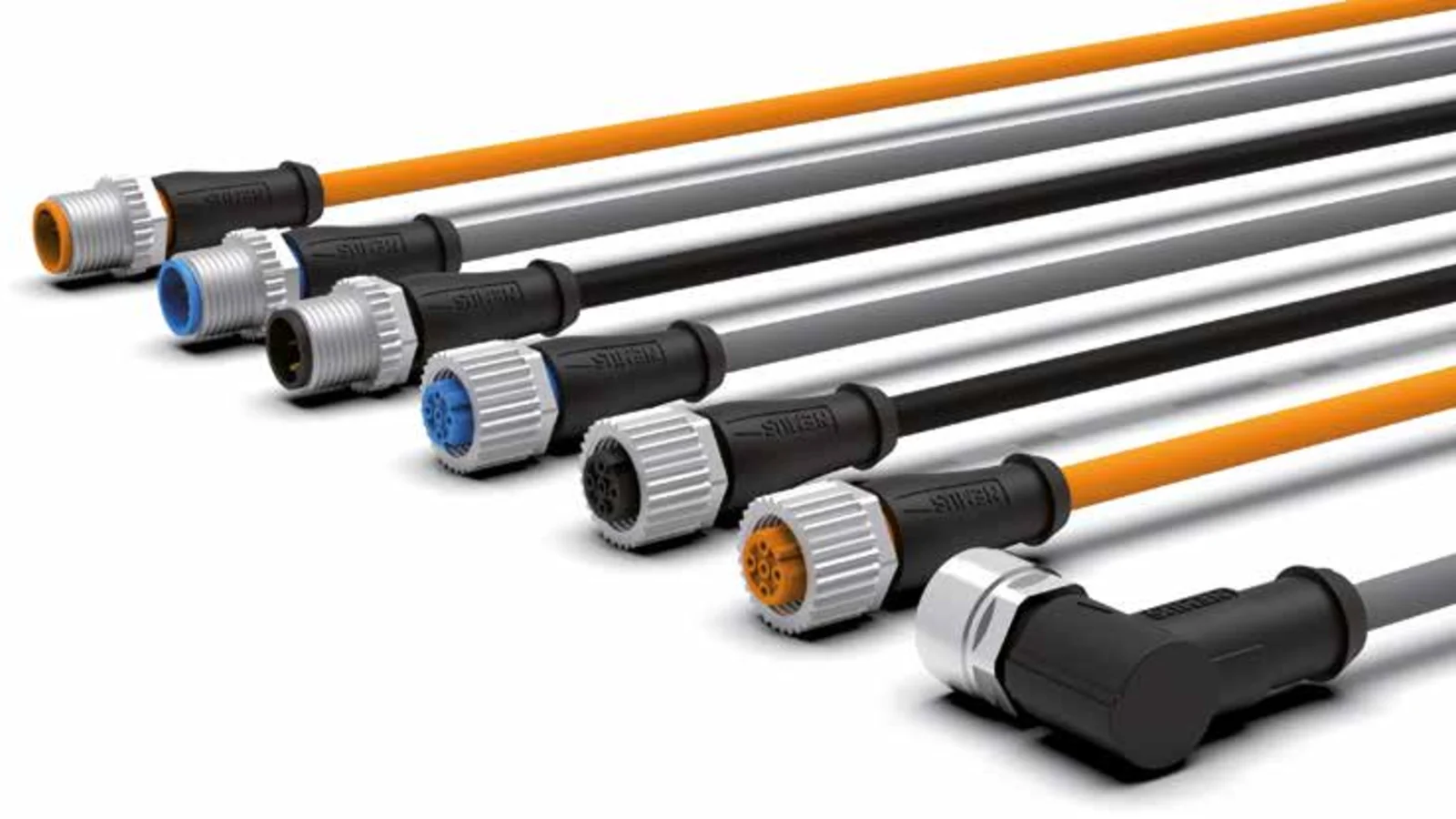
In a circuit where both ends are equipped with pre-installed sockets, a double-sided cable set provides a more suitable solution. Nemus’ catalog lists male and female connectors, 0° and 90° body angles, and various combinations of these options separately. This diversity ensures that the cable not only fits the electrical schematic but also conforms to the physical layout requirements. However, it is not sufficient for the mechanical connections at both ends to be correct; the number of contacts and the function of each pin must also be verified according to the connection tables of the two devices. It is particularly important to remember that in the case of M12-M8 transitions, a physical adaptation does not necessarily imply compatibility of the signals.

Panel-side termination with open-ended cables
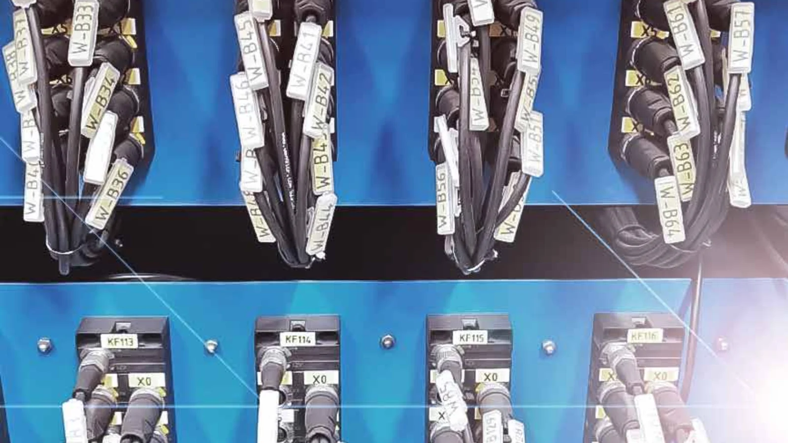
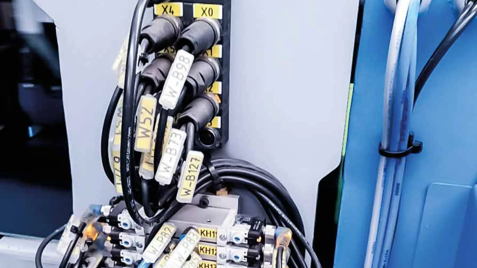
In the cable connectors with open ends listed in the Nemus catalog, the M8 or M12 connections on the device side are pre-molded during manufacturing; the other end is connected to the terminals required by the specific electrical project. This design enables field devices to be easily removed and the internal wiring within the control panel to be arranged according to the specific project requirements. The color of the conductors at the open ends should not be relied upon alone to determine their function. It is essential to compare the product code’s connection diagram with the device manufacturer’s pin layout, and the conductors must be labeled with the terminal numbers specified in the panel design.
At the panel entrance, the bending radius of the cable, the pulling force, the cable gland, and the overall sealing requirements must all be taken into consideration. The IP65, IP66K, or IP67 rating indicated on the connector does not define the protection level of the panel gland or the exposed end of the cable. When the cable is inserted into the panel, appropriate glands and mechanical fixing devices must be selected; the panel’s protective conductors and grounding system must also be designed according to the project requirements. When the panel cover is opened, it is essential to ensure that the cable does not exert any strain on the terminals, that the clearances around the conductors are maintained properly, and that the power and signal circuits are arranged in accordance with industry standards.
M12 connections: sensor and actuator links between the panel and field
M12 A series products offer a wide range of configuration options for connecting sensors and actuators in machine automation applications. Nemus’ catalog features options with 3, 4, or 5 contacts, male or female connectors, straight or 90° orientations, and single- or double-sided configurations. The standard M12 connectors specified in these catalogs have a conductor cross-section of 0.34 mm² and a nominal current rating of 4 A per contact. The maximum operating voltage ranges from 250 V for four-contact connectors to 125 V for five-contact connectors; however, these values should be confirmed based on the specific configuration and product code selected.
M12 field-mounted connectors are also available in 3-, 4-, or 5-contact versions, and come in both male and female types, as well as straight and 90° angles. Product specifications indicate maximum conductor cross-sections of up to 0.75 mm², as well as options depending on the cable outer diameter. These products can be used when it is necessary to terminate an existing cable on a machine or to create a connection interface during maintenance. Since the installation quality directly affects the final outcome, procedures such as conductor preparation, screw connection, gasket placement, and clamping must be carried out in accordance with the manufacturer’s instructions.
M8 connections: compact machine connection points
M8 A code connectors offer a compact connection option in machine areas where space around sensors is limited. The molded M8 cable sets listed in the Nemus catalog are available in 3- and 4-contact configurations, as well as male or female versions, and with 0° or 90° mounting angles. The technical specifications indicate a conductor cross-section of 0.25 mm², a maximum operating voltage of 50 V AC or 60 V DC for 3- and 4-contact versions, and a nominal current of 4 A per contact. When selecting an M8 interface, it is essential to consider both the electrical specifications and the space-saving advantages of its compact design.
In the M8 field-mounted types, the catalog offers options featuring 3- or 4-contact straight connectors, as well as 90° male-to-female connectors. This family of products specifies a maximum conductor cross-section of 0.50 mm² and cable outer diameters ranging from 2.5 to 5 mm. Field-mounted connections are not necessarily superior to pre-fabricated, molded cables; they prove useful in scenarios where the cable length cannot be determined in advance, where existing cables must be used, or where ease of maintenance is a top priority. When considering production volume, molded sets with high repeatability should be preferred; however, in applications requiring flexibility on-site, field-mounted products installed using the correct procedures offer a more viable solution.
Moulded cable assemblies or field-assembled connectors?
| Project situation | Solution to consider | Control point |
|---|---|---|
| A direct connection from the device to the control panel. | An M8 or M12 cable with an open end at one end | Connector orientation, cable length, conductor-pin alignment, and panel connection points. |
| Connection between two pre-installed sockets | Dual-sided cable set | At both ends, there are considerations regarding gender, angle, number of pins, and signal compatibility. |
| Transition from M12 device to M8 interface. | M12-M8 double-ended cable | In addition to the physical connection, electrical pin compatibility is also required. |
| Terminating the existing cable on-site. | M8 or M12 field-mounted connector | Cable outer diameter, conductor cross-section, installation method, and sealing. |
| Unused M12 female connectors | Appropriate dust cover | Thread size, seal, correct tightening, and manufacturer compatibility |
In prefabricated cable sets, the connector body and the cable connection are manufactured during the production process. Nemus states that it applies electrical tests, high-voltage tests, performance evaluations, pin-to-pin checks, short-circuit tests, and visual inspections to these products, and tests 100% of the connectors produced. Field-mount connectors enable the cable length to be adjusted at the installation site, allowing the use of existing cables; however, the consistency of the installation outcome depends more heavily on the preparatory work and clamping procedures carried out by the user. Project specifications should clearly define in advance which of these two approaches should be used in each particular case.
Select the cable sheath for the actual movement
One of the most common mistakes in machine selection is judging a cable solely based on its appearance, such as the color of the coating or its outer appearance. Nemus’ general catalog classifies PVC cables as a cost-effective solution for fixed applications, PVC+ cables as a suitable option for movable applications, and PUR cables as high-performance solutions for dynamic and robotic environments. Cables that remain fixed in place within a machine and those that are continuously bent within the cable carriers should not be considered as the same product. Additionally, the movement patterns of cables used in applications involving door operations, axis movements, or attachments to vibrating components must also be carefully considered.
In catalog comparisons, it is stated that for PVC+ materials with a dynamic bending radius requirement, the number of operating cycles ranges from 3 to 5 million; for PUR materials, this range is 4 to 6 million cycles. The relevant tables specify acceleration values of 10 m/s² and a speed of 180 m/min for PVC+, as well as 30 m/s² and 240 m/min for PUR. These values are meaningful in the context of the manufacturer-defined bending radius and test conditions and should not be used alone as a guarantee for field service life. Factors such as torsion, pulling forces, the degree of filling in cable chains, temperature, stroke length, and chemical exposure can all affect actual performance. The path of movement for each axis and the minimum required bending radius must be verified separately for each application.
The IP rating applies to the complete connection chain
Nemus specifies the IP65, IP66K, and IP67 ratings in its molded M8 and M12 product tables. For field-mounted types, the IP67 rating is also indicated, provided that the connection is properly installed and tightened. Failure to meet these conditions—such as leaving unused sockets unsealed, failing to fully tighten the connector, damaging the seal, or using incompatible components—will invalidate these ratings. If the connection is located in a washdown area, the orientation of the connector, the potential for water flow along the cable, and re-tightening checks after maintenance must also be taken into consideration.
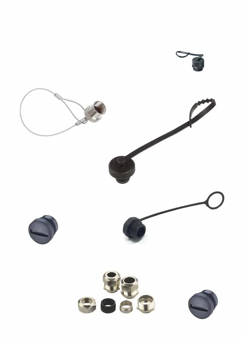
The catalog specifies separate dust covers and tethered dust caps for M12 female connections. These accessories are designed to protect unused connection points; however, it should not be assumed that they are universally suitable for any open terminal. The M12×1 mm thread pitch and IP67 rating listed in the catalog apply only when the components are properly installed and tightened. If the connection is left open during the machine’s maintenance mode for an extended period, it is necessary to determine the appropriate sealing device, cleaning method, and re-commissioning procedures.
Electrical compatibility and pin assignments
The terms “M8” or “M12” merely refer to the mechanical family of connectors; they do not define the entire system design. The number of contacts, A-code wiring direction, the functional roles of each pin for power and signal transmission, the PNP/NPN device configuration, and the input/output layout of the control equipment must all be carefully matched according to the project specifications. Although Nemus’ catalog provides color codes for cables, users should not assign pin functions solely based on color. It is essential to verify the continuity of connections by examining cable and device diagrams, and ensure that the connector label on the control panel matches the corresponding device label, both referring to the same specific component.
The electrical specifications should not be generalized merely based on the product family name. For representative M12 and M8 molded products, a current rating of 4 A is specified per contact; the voltage values, however, vary depending on the number of contacts and the product family. The cross-sectional area of the conductors and the maximum outer diameter of the cables acceptable for field-mounted types differ from those of molded cables. The device, connector, cable, and terminal installed in the circuit should be considered as the determining factor for the minimum electrical specifications; short-circuit protection measures and voltage drop calculations should be applied to the entire circuit.
The correct scope of UL/CSA approval
On Nemus’s catalog pages, terms such as UL AWM, UL 1581 FT-1, and UL/CSA are used to refer to certain types of cables. The same catalog clearly states in a footnote that UL/CSA standards apply to these cables. Therefore, when referring to a “UL/CSA-certified cable connector” in a project, it should be specified that the certification applies specifically to the cable component, and it should not be inferred that the entire connector assembly possesses independent UL/CSA certification. For field-installed products, the catalog indicates certifications such as CE and RoHS, but UL/CSA is not listed in the same manner.
If a machine standard requires specific certifications or traceability, reliance solely on the catalog summary is not sufficient. For the selected order code, a current compliance declaration must be obtained, and the product family and scope specified in the documentation must be verified. In particular, it should not be assumed that the same certification applies when the cable sheath, color, length, or motion class are changed. The product code, data sheet version, and applicable installation instructions must all be retained in the technical documentation.
Project planning for machine and panel connections
- Create a point list: Record the device label, socket family, number of contacts, and pin functions for each sensor, actuator, and I/O connections.
- Determine the connection type: Decide whether to use a cable with an open end that requires panel termination, a double-sided cable between two sockets, or a field-mounted solution.
- Check the mechanical layout. Verify the straight or 90° orientation of the outlet, as well as the space required to tighten the connector and the distance necessary for safe disconnection during maintenance.
- Measure the length of the cable: Calculate length from the actual route, service allowance, stroke, and bend conditions inside the cable carrier.
- Describe the environmental conditions: When selecting a product, take into account the effects of temperature, oil, cleaning chemicals, vibration, UV radiation, dust, and water.
- Complete the protection chain: Evaluate the connector, mating socket, panel gland, and unused-port covers against the same IP protection target.
- Plan the commissioning test: Record inspections for label placement, pin continuity, polarity, functionality, and mechanical tightness.
- Establish maintenance standards: Add the critical product codes to the spare parts list; regularly inspect the cover, cable, and seal surfaces.
Information required for a quotation
- M8, M12, or M12-M8 interface; the male-female configuration of the A code and the corresponding socket.
- The number of contacts and the electrical function of each pin
- Options for a 0° or 90° body angle, along with the required combinations for both ends.
- A decision regarding the type of connection to be open-ended, bilateral, or installed on-site.
- Information on voltage, rated current, cable cross-section, and voltage drop.
- The choice between PVC, PVC+, or PUR is determined by the required fixed/movable application profile.
- Route length, bending radius, acceleration, speed, and expected cycle time.
- Temperature, oil, chemicals, water, dust, UV radiation, and vibration conditions.
- The scope of the certification, based on the required compliance documents and the product code.
Once these details are clarified, Nemus products become a reliable selection system for connecting sensors and actuators between the control panel and the machine within this scope. Oskon can determine the appropriate connector family, terminal orientation, cable configuration, and length by considering the I/O list, field devices, and mechanical layout. The final product code must be confirmed in accordance with Nemus’s current technical documentation, manufacturer’s installation instructions, compliance certificates, and the electrical and mechanical standards of the facility.